AME 3623: Project 5: Rate Gyroscopes and Damping Control
Key to successful control in embedded systems is the ability to
integrate information about the external state of your system into the
control decisions that are being made. In this project, we will
finally close a loop between sensing and actuation. We will
add one more component to your circuit: an inertial measurement unit
(IMU). The IMU contains three distinct sensors (with three degrees of
freedom each): an accelerometer, a rate gyroscope and a magnetometer.
The gyroscope will be used in this project to dampen rotational
disturbances. In project 6, we will use all nine degrees-of-freedom
to estimate the orientation of the hovercraft.
- All components of the project are due by Friday, March 29th
at 11:59 pm.
- Groups are the same as for project 1.
- Discussion within groups is fine.
- Discussion across groups may not be about the specifics of the
solution (general programming/circuit issues are fine to
discuss).
At the end of this project, you should be able to:
- extract rotation rate information from an inertial measurement unit, and
- use the sensory data to dampen out rotational disturbances.
Component 0: Library Installation
The new library provides the following functions:
Component 1: Hardware and Circuit
In order for your hovercraft to lift off the floor, it must be
balanced. Move your circuit board into a position such that your
craft is balanced front-to-back and left-to-right. We will be
providing battery mounts for this purpose.
Inertial Measurement Unit
The IMU is a MPU-9250. Mount the Inertial Measurement (IMU) on the
mast that we provide. The advantage of the mast is that your sensor
will be less subject to magnetic interference from the hovercraft motors
and wires, as well as sources buried in the floor.
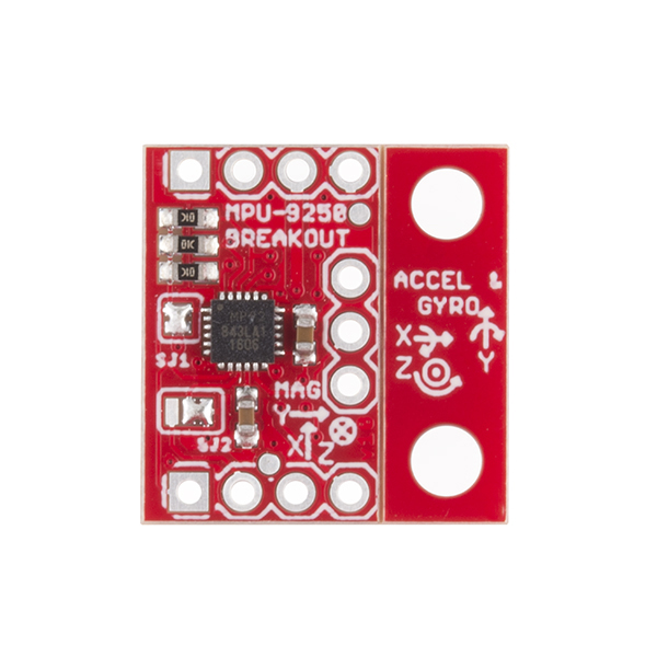
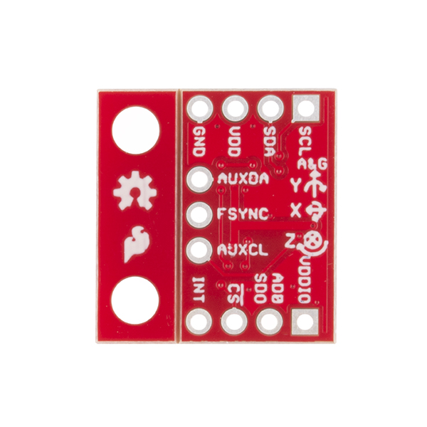
Connect the IMU to your circuit. The pins are:
- BLACK Ground
- +3.3V power: connect to the 3.3V supplied by the Teensy
- SDA: connect to SDA0 of the Teensy (Arduino pin 18)
- SCL: connect to SCL0 of the Teensy (Arduino pin 19)
Central Fan
- Once your new central fan has been installed, it will be hard-wired
into the +11V switched power supply. This connection provides power
to the fan's control circuitry and to the fan motor.
- The remaining connector has two pins: ground (black) and
torque magnitude (white). Connect ground to your processor's
ground and the torque magnitude signal to a free PWM pin.
Component 2: Software
-
Copy the following function from project 1:
- void display_heading_velocity(float velocity)
-
Copy the functions that you developed in project 4 into your current project.
- Add the following code to the top of your program
PWMServo fan;  // create servo object to control the fan
const int CENTRAL_FAN_PWM = ???;

void fan_setup() {
     fan.attach(CENTRAL_FAN_PWM);  // attaches the fan to specified
                                   //   Arduino pin to the object
     delay(100);
     fan.write(20);  // write low throttle
     delay(3000);
}
Make sure to call this new function from setup()
- Implement a new PeriodicAction (called sensor_task)
that executes once per 5 ms
The associated sensor_step() function should:
- Call imu_update().
- Display the rotation velocity of the craft.
-
Implement the following function:
void set_hovercraft_forces(float fx, float fy, float torque)
This function accepts as input desired forces to be applied to
hovercraft chassis, translates these desired forces into an
appropriate thrust level for each of the lateral fans, and
changes the thrust state of these fans. Note that the precise
units of these forces are not really known (don't worry, the
units will "wash away" once we introduce our control gains).
- Implement a new finite state machine in fsm_step(). This state
machine will:
- Ramp up the central fan to a 50-70% duty cycle in 5
seconds (use the smallest level that brings the craft off
the ground).
You can set the duty cycle of the central fan using:
fan.write(duty)
where the duty parameter is a value between 0 and 255
(corresponding to zero to 100% duty cycle)
- Wait in this state for 30 seconds.
- Ramp down the central fan to zero.
- Implement a new PeriodicAction (called control_task
that executes once per 10 ms. The associated
control_step() function will implement a damping
rotation controller. Specifically:
float fx = 0.0;
float fy = 0.0;
float torque = Kv * IMU.gz;   // gz = gyro about the Z axis (right-handed coord frame)
set_hovercraft_forces(fx, fy, torque);
- Add each of your tasks to your loop() function.
Component 3: Testing
- Perform initial testing while holding the lip of the Hovercraft
with two hands (I recommend not sticking fingers in the fans).
- Start with a conservative Kv (i.e., a small value).
- Slowly increase the gain until the craft
resists the rotations.
- At this point, you can place the craft on the floor (or a
table, if you are careful).
- If the craft tends to oscillate while on the ground, then
decrease your Kv.
What to Hand In
All components of the project are due by Friday, March 29th at
11:59 pm
- Demonstration/Code Review: All group
members must be present. Given time, this can be done during
class. The demonstration must be completed by Tuesday April 4th.
- Check in the following to your project 5 area of your Dropbox:
- Personal report: Catme will request that you fill out a
survey about the project. These must be completed by Tuesday
April 4th in order to receive credit for the project.
Grading
Personal programming credit:
- Each person must accumulate at least three personal programming
credits over the course of the semester.
- To receive credit, you must be the primary designer,
implementer and debugger of the component. This does
not mean that your other group members should not be looking
over your shoulder. But: you must do the "driving."
Group grade distribution:
- 35%: Project implementation
- 30%: Demonstration of working project (to either
of the TA or the instructor)
- 35%: Documentation
Group Grading Rubric
Grades for individuals will be based on the group grade, but weighted
by the assessed contributions of the group members to the non-personal programming items.
andrewhfagg -- gmail.com
Last modified: Sat Mar 30 00:03:35 2019