At the end of this project, you should be able to:
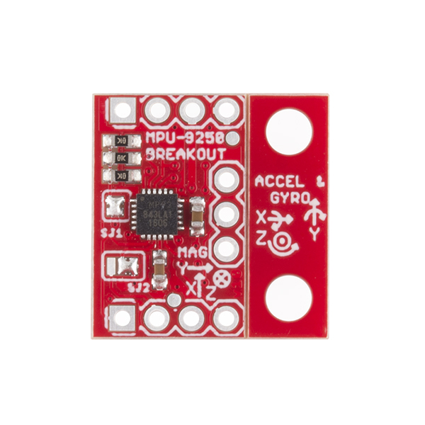
The IMU is a MPU-9250. Mount the Inertial Measurement (IMU) on the mast that we provide. The advantage of the mast is that your sensor will be less subject to magnetic interference from the hovercraft motors and wires, as well as sources buried in the floor.
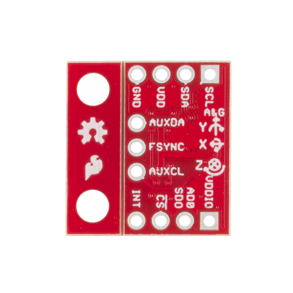
Connect the IMU to your circuit. The pins are:
This function accepts as input a desired acceleration of the hovercraft, translates this desired acceleration into an appropriate thrust level for each of the lateral fans, and changes the thrust state of these fans.
The control_step() function has already been provided for you (below). Modify this function to add the following functionality:
       float ddx = 0.0;
       float ddy = 0.0;
       float ddtheta = -Kv * rotation_rate;
       set_hovercraft_acceleration(ddx, ddy, ddtheta);
#include "PeriodicAction.h"
#include "MPU9250.h"

// Promise that we will implement this function later
void control_step();

// Create a task that will be executed once per 10 ms
PeriodicAction control_task(10, control_step);

// Create a connection to the inertial measurement unit
MPU9250 IMU;

/**
   Initialize the IMU and verify that it is functioning.

   References: MPU9250 Basic Example Code, Kris Winer (April 1, 2014)
*/
void setup_imu()
{
  // Initialize the I2C bus (to which the IMU is connected)
  Wire.begin();

  // Test the connection to the IMU
  byte c = IMU.readByte(MPU9250_ADDRESS, WHO_AM_I_MPU9250);

  if (c == 0x71) {
    Serial.printf("IMU initialized successfully\n");
  } else {
    Serial.printf("*** UNABLE TO CONTACT IMU ***\n");
    // Loop forever
    while (1) {
      delay(10);
    }
  }

  // Calibrate the gyros and accelerometers.
  // NOTE: THE HOVERCRAFT MUST BE STATIONARY DURING THIS CALIBRATION
  IMU.calibrateMPU9250(IMU.gyroBias, IMU.accelBias);

  // Initialize the IMU
  IMU.initMPU9250();

  // Check the magnetometer
  c = IMU.readByte(AK8963_ADDRESS, WHO_AM_I_AK8963);
  if (c == 0x48) {
    Serial.printf("Magnetometer initialized successfully\n");
  } else {
    Serial.printf("*** UNABLE TO CONTACT MAGNETOMETER ***\n");
    // Loop forever
    while (1) {
      delay(10);
    }
  }

  // Retrieve magnetometer calibration
  IMU.initAK8963(IMU.magCalibration);
}


void setup() {
  // Initialize the USB serial connection
  Serial.begin(115200);

  // Initialize the IMU
  setup_imu();

  // Add your project-specific setup code here

}

/**
   Update the state of the IMU by reading calibrated linear acceleration and rotation
   rate information.

   Inputs:
    n/a
   Outputs:
    (implicit): the state of variables IMU.ax, IMU.ay and IMU.az encode linear acceleration in
                  g/sec
    (implicit): the state of variables IMU.gx, IMU.gy and IMU.gz encode rotation rate in
                  deg/sec

   References: MPU9250 Basic Example Code, Kris Winer (April 1, 2014)
*/
void update_imu()
{
  // Read the accelerometer values and compute calibrated accelerations
  IMU.readAccelData(IMU.accelCount);
  IMU.getAres();
  IMU.ax = (float) IMU.accelCount[0] * IMU.aRes;
  IMU.ay = (float) IMU.accelCount[1] * IMU.aRes;
  IMU.az = (float) IMU.accelCount[2] * IMU.aRes;

  // Read the gyros and compute calibrated velocities
  IMU.readGyroData(IMU.gyroCount);
  IMU.getGres();
  IMU.gx = (float)IMU.gyroCount[0] * IMU.gRes;
  IMU.gy = (float)IMU.gyroCount[1] * IMU.gRes;
  IMU.gz = (float)IMU.gyroCount[2] * IMU.gRes;
}

/**
 * Single sensing & control step
 *
 * Note: delays are allowed in this function (or any function called by this function)
 */
void control_step()
{
  // Update the state of the IMU
  update_imu();

  // Count the number of times that this function has been called
  static unsigned long counter = 0;

  // Increment the counter (1 per 10 ms)
  counter++;

  if(counter < 500) {
    // Ramp up the central fan to 100%


  }else if(counter < 6500) {
    // Implement control law here

  }else if(counter < 7000) {
    // Ramp down the central fan to 0%

  } // Else do nothing
}

/**
 * No changes necessary to the loop (except to add new tasks)
 */
void loop() {
  // Check to see if it is time to execute the control_task
  control_task.step();
}
Grades for individuals will be based on the group grade, but weighted by the assessed contributions of the group members to the non-personal programming items.
Last modified: Thu Mar 30 01:34:15 2017