AME 3623: Project 7: Compasses and Position Control
- All components of the project are due by Thursday, April 14th
at 9:00 am
- Groups are the same as for project 1.
- Discussion within groups is fine.
- Discussion across groups may not be about the specifics of the
solution (general programming/circuit issues are fine to
discuss).
At the end of this project, you should be able to:
- extract hovercraft orientation from a magnetometer sensor, and
- use the sensory data to drive the motors in such a way that the
craft will orient toward a goal.
Component 1: Circuit
Connect a compass to your circuit. We have two different types of
sensors for the class; your group has one.
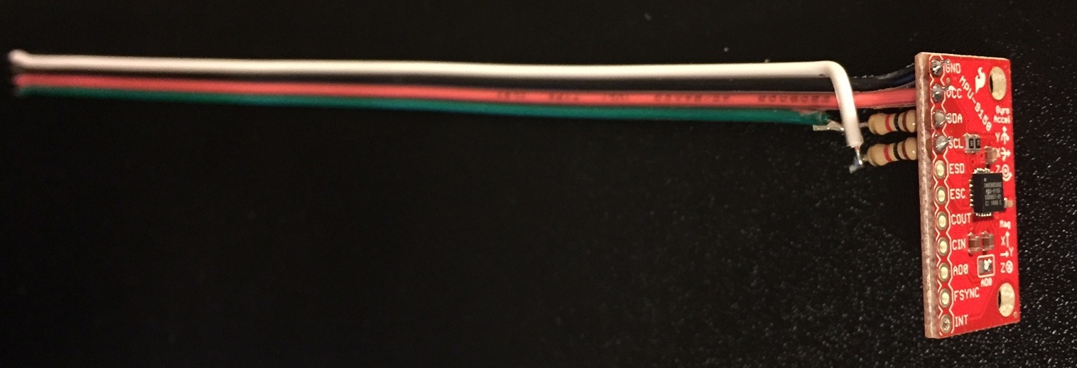
Combined Compass/Gyro/Accelerometer
For those of you who have the "long-stem" gyros for project 6 (labeled
MPU-9150), then you already have a compass. You do not
need to do additional wiring.
Access:
- Initialization is the same process as for project 6.
- The library also provides:
void imu_calibrate_compass_full(FILE *fp); will go
through a calibration procedure that you must use to ensure
quality compass headings. When you call this function, it will
ask you to begin to slowly turn your sensor (about the Z axis);
your goal is to
make two complete rotations in about 15 seconds (remember to
keep the sensor flat during this time). Once complete, the
compass will be calibrated and usable, and this function will
print out a line of code that you can drop right
into your main program initialization procedure that can be
called in lieu of
imu_calibrate_compass_full().
uint16_t imu_read_compass_full(void); returns the compass
heading in units of 1/(2^16) of a full rotation (i.e, fixed
point "0.16" format) in a left-handed coordinate frame.
Specifically: 0 = magnetic north, 0x8000 = PI, and 0xFFFF = PI * (2 - 1/32768).
Notes:
- The IMU sensor should be mounted such that it stays flat at all
times.
- You should only calibrate your compass after it is mounted.
- Once you receive the offset values from the calibration
function, you can use these directly with
imu_set_compass_params_full(). This means that you won't have to
recalibrate the compass every time you start your program.
Compass-Only Sensor
These compass modules also have "long-stems". You have this compass
if you have a short-stem gyro.
- Connect the compass module to your microcontroller. The compass pin assignment is as follows:
- Ground
- space (no pin)
- Power (5v)
- SDA
- SCL
- When mounting the compass to your hovercraft, you should place
it as far away as possible from
the motors and from other wires. In addition, the compass must
be flat and steady. We have provided some 3D-printed supports
to aid with stability. These are either in your kit or are
available in FH 300.
Access:
- You will be using the following files in your oulib folder:
compass.h, i2c_isr.h and libcompass_atmega2560.a
- Set up your new project in Atmel Studio as you normally would.
However:
- Add compass.h and i2c_isr.h to your list of includes (Solution Explorer)
- Add #include "compass.h" to the top of your C
file (below your other includes).
- Add compass_atmega2560 to your list of libraries
(Project Properties / Libraries)
- If you are using OSX: replace the following line in your
makefile:
OU_LIB = -L$(OULIB_DIR)/lib -lou_$(MCU)
with:
OU_LIB = -L$(OULIB_DIR)/lib -lcompass_$(MCU) -lou_$(MCU)
Don't forget to add #include "compass.h" to the top
of your C file (below your other includes).
- This new library provides an initialization function:
void compass_init(); initializes the compass
interface. Call this toward the top of your main() function.
- The library allows you to read from the compass:
int16_t compass_query() returns the current
heading of the compass. The return value is in 1/10's of a
degree in a left-handed coordinate system, and the range is 0
... 3599. A value of zero
corresponds to magnetic North.
- There are also two calibration functions (you may or may not
need to use them):
Call compass_calib_start() to begin the calibration
procedure, delay for ~10 seconds, and then call
compass_calib_end(). Between these two calls, you
must slowly rotate your sensor a full two turns. Once you have
completed the calibration procedure, the compass module will
store the parameters. This means that moving forward, you will
not need to recalibrate.
Both Compass Types: Testing your Compass
Before using your compass to control your hovercraft, you should test
the compass to confirm that it is well calibrated. The best approach
is to implement a while(1) loop that queries the sensor heading,
prints it out and delays for a short time (e.g., 100ms). Zero degrees
should correspond to magnetic North. Turning your compass to
each of the cardinal directions (East, South, West), your program
should report angles close to 90, 180 and 270 degrees. If these
values are substantially different, then your compass needs to be
recalibrated. See the instructor or the TA for help on this if you
are having trouble.
Remember that you should calibrate your compass while it is on your
hovercraft and far away from other magnetic sources.
Component 2: Software
Implement the following functions:
Copy all of your functions from project 6, and copy the following
function from project 1:
- void display_heading(int16_t theta)
Structure your main() function as you did for project 6. Except:
- Add other necessary initialization.
- Within your loop, make calls to read and display your current
rotation error.
- Call your position_control() function (replacing derivative_control()).
Your main function should still ramp-up the middle fan, stopping once
the craft begins to turn. Afterwards, perform 30 seconds of hovering
while maintaining a heading toward the selected goal. During this time, the
hovercraft will oscillate around its goal since we do not have damping
turned on; this is OK for this lab. After the 30 seconds has passed,
your craft must slowly ramp down the middle fan.
Component 3: Testing
- Slowly decrease the divisor until the craft aggressively
tries to maintain the goal orientation.
- At this point, you can place the craft on the floor (or a
table, if you are careful).
- The craft should produce a thrust with the left fan if the goal
is anywhere to the right and a thrust with the right fan if the
goal is anywhere to the left. Which fan is turned on will
switch at a 180 degree error.
What to Hand In
All components of the project are due by Thursday, April 14th at
9:00 am.
- Demonstration/Code Review: All group
members must be present. Given time, this can be done during
class. The demonstration must be completed by Monday, April 18th.
- Check in the following to your project 7 area of your
subversion tree:
- Personal report: fill out the CATME survey. This is due
by Tuesday, April 19th at 11:59pm.
Grading
Personal programming credit:
- Each person must accumulate at least three personal programming
credits over the course of the semester. This project offers
one credit.
- To receive credit, you must be the primary designer,
implementer and debugger of the component. This does
not mean that your other group members should not be looking
over your shoulder. But: you must do the "driving."
Group grade distribution:
- 35%: Project implementation
- 30%: Demonstration of working project (to either
of the TA or the instructor)
- 35%: Documentation
Group Grading Rubric
Grades for individuals will be based on the group grade, but weighted
by the assessed contributions of the group members to the non-personal programming items.
References
andrewhfagg -- gmail.com
Last modified: Wed Apr 13 14:50:02 2016