AME 3623: Project 7: Rate Gyroscopes and Damping Control
Key to successful control in embedded systems is the ability to
integrate information about the external state of your system into the
control decisions that are being made. In this project, we will
finally close a loop between sensing and actuation. We will
add one more component to your circuit: an inertial measurement unit
(IMU). The IMU contains three distinct sensors (with three degrees of
freedom each): an accelerometer, a rate gyroscope and a magnetometer.
The gyroscope will be used in this project to dampen rotational
disturbances. In project 8, we will use all nine degrees-of-freedom
to estimate the orientation of the hovercraft.
- All components of the project are due by Tuesday, April 13th
at 5:00 pm.
- Groups are the same as for project 1.
- Discussion within groups is fine.
- Discussion across groups may not be about the specifics of the
solution (general programming/circuit issues are fine to
discuss).
At the end of this project, you should be able to:
- extract rotation rate information from an inertial measurement unit, and
- use the sensory data to dampen out rotational disturbances.
Component 0: Library Installation
The new IMU Utils library provides the following functions:
Component 1: Hardware and Circuit
If your craft isn't balanced yet, it is now time to do this.
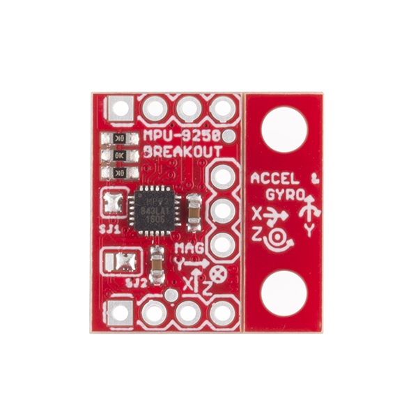
Inertial Measurement Unit
The IMU is a MPU-9250. Mount the Inertial Measurement (IMU) on the
mast that we provide. The advantage of the mast is that your sensor
will be less subject to magnetic interference from the hovercraft motors
and wires, as well as sources buried in the floor. Make sure that
your mast is intact and be gentle with it (don't crush it and don't
grab your hovercraft by it).
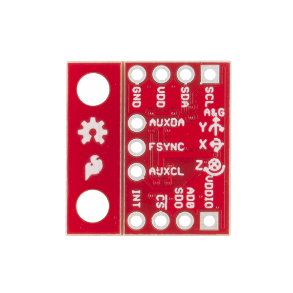
Connect the IMU to your circuit. The pins are:
- BLACK Ground
- +3.3V power: connect to the 3.3V supplied by the Teensy
- SDA: connect to SDA0 of the Teensy (Arduino pin 18)
- SCL: connect to SCL0 of the Teensy (Arduino pin 19)
Component 2: Software
-
Copy the functions that you developed in project 6 into your current project.
- Implement a new PeriodicAction (called imu_task)
that executes once per 5 ms
The associated imu_step() function should:
- Implement a new finite state machine in fsm_step(). This state
machine will:
- Wait for the switch to be pressed.
- Spin up the central fan.
- Wait in this state for 30 seconds.
- Turn off the central fan.
- Return to waiting for the switch.
- Implement a new PeriodicAction, called pd_task,
that executes once per 10 ms. The associated
pd_step() function will implement a damping
rotation controller. Specifically:
float fx = 0.0;
float fy = 0.0;
float torque = Kd * IMU.gz;   // gz = gyro about the Z axis (right-handed coord frame)
set_hovercraft_forces(fx, fy, torque);
- Implement a new PeriodicAction, called report_task,
that executes once per second. The associated
report_step() function will print out the current
rotation rate (IMU.gz).
- Add each of your tasks to your loop() function.
Component 3: Testing
- Perform initial testing while holding the lip of the Hovercraft
with two hands (I recommend not sticking fingers in the fans).
- Start with a conservative Kd (i.e., a small value).
- Slowly increase the gain until the craft
resists the rotations.
- At this point, you can place the craft on the floor (or a
table, if you are careful).
- If you spin your craft, then the craft should respond by
slowing down the rotation quickly (a fast initial rotation
should be damped out in about one second).
- If the craft tends to oscillate while on the ground, then
decrease your Kd.
- If the craft drifts laterally a lot while it is damping out
rotations, then you need to revisit your negative_gain parameters.
What to Hand In
All components of the project are due by Tuesday, April 13th at
5:00 pm
- Demonstration/Code Review: All group
members must be present. The demonstration must be completed
by Friday, April 16th.
- Check in the following to your project 7 area of Gradescope:
- Personal report: Catme will request that you fill out a
survey about the project. These must be completed by April 16th
in order to receive credit for the project.
Grading
Project lead credit:
- Each person must be the primary integrator of circuits and code
for two projects over the course of the semester.
For a successful project, we expect:
- A properly configured circuit
- IMU is properly connected to your processor
- Properly written software
- imu_step()
- pd_step()
- report_step()
- Finite State Machine implementation
- Properly documented code
- Project-level documentation at the top of the ino file:
name and group number, date and project number
- Function-level documentation above the function
definition. Include an abstract description of what the
function does; a list of the names, types and units
associated with each parameter and return value; and the
effects that the function has on the processor or
connected components.
- In-line documentation inside of functions: individual
lines or small groups of lines have an English
description that describes logically what the code is doing
andrewhfagg -- gmail.com
Last modified: Sat Mar 27 15:29:40 2021